|
Installation Pictures
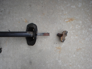
(Removing the OEM steering box flange)
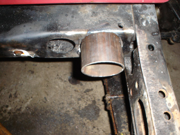
(Preparing the cross member tube for install)
.jpg)
(Steering Box Plate After Spacers Have Been Matched to Gear Box)
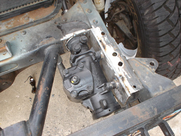
(Installed cross member tube & plate, check for fit with steering box)
.jpg)
(Installed cross member tube & plate, check for fit with steering box)
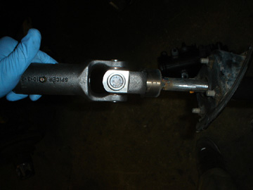
(Top slip-joint assembly, welded to OEM steering shaft, late model FJ40)
 (2).jpg)
(Top slip-joint assembly, welded to OEM steering shaft, early model FJ40)
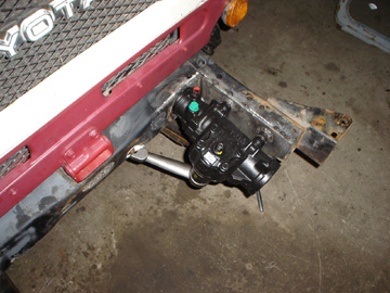
(Completed steering box installation)
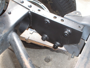
(Completed steering box plate & cross member tube installation)
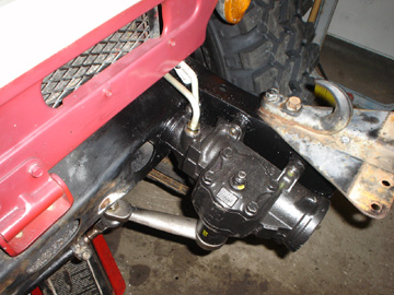
(Finished power steering system)
Installation Instructions (Rough Draft)
Step 1: Remove the Stock Steering Column
A: Unplug or remove turn signal and horn switch assemblies.
B: Remove the two bolts and rubber mount under the dash panel.
C: Remove the 6 bolts at the firewall on early models and the 3 bolts on later model Land Cruisers.
D: On early models (key on dash), cut steering at the steering box. This will be trimmed later so you don't need to be precise. On later models (key on column). Cut the steering box flange off of the steering shaft, approximately 1" from the end. This will be trimmed later so you don't need to be precise.
Step 2: Remove Existing Parts
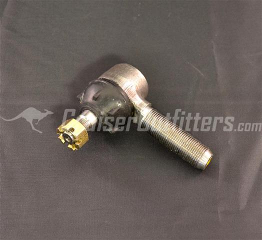
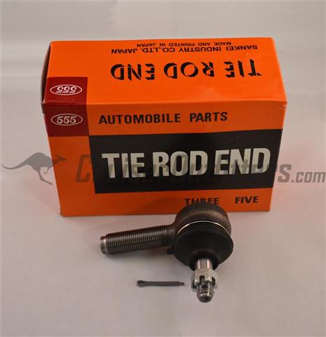
A: Remove stock drag-link and relay rod's completely from the vehicle. You will be re-using the stock passenger side drag-ling end so take care not to damage the end.
B: Remove the stock steering damper from the center arm and the frame side mount
C: Remove the center arm assembly, no part of this will be re-used.
D: Remove the stock steering box and mount from the frame, this will require grinding or torch cutting the rivets that attach it to the frame. Clean up and paint the frame following removal.
Step 3: Column Prep and Install Bushing or Bearing
(For Early-9/1972 Models)
A: Cut factory steering column tube (outer tube) approximately 6" forward of the firewall.
B: Cut factory steering column shaft (5/8" shaft) approximately 4" forward of that location, so the shaft should protrude approximately 10" forward of the firewall.
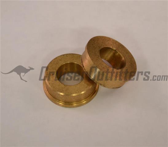
C: Clean steering shaft lightly with sand paper or flap wheel until the brass column bushing (Part# PSCB1) will slide up the shaft and seat into the outer steering column tube with a near press fit.
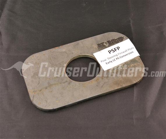
D: Prepare firewall plate (Part# PSFP) by aligning plate with existing hole in firewall. Transfer bolt hole locations on the firewall to the firewall mounting plate. Remove and drill holes in firewall plate.
E: Remount steering column in vehicle. Prep steering column tube at firewall and mount firewall mounting plate so that shaft is positioned through the center of the firewall hole. Tack weld firewall plate to steering shaft tube.
F: Remove steering column assembly. Finish weld firewall plate, prep and paint. Remount steering column temporarily for fitment of steering shaft kit in engine bay.
(For 9/72-1984 Models)
A: Cut factory steering column shaft ~10" from firewall mounting plate.
B: Remove column firewall plate by removing the 4 bolts from the steering shaft tube.
C: Clean steering shaft lightly with sand paper or flap wheel until the column rolling bearing (Part# PSCB2) will slide up the shaft and seat into the outer steering column tube with a near press fit.
D: Replace the column firewall plate, this will lock the column bearing into place permanently.
E: Remount steering column temporarily for fitment of steering shaft kit in engine bay.
Step 4: Steering Box Plate Prep & Tack-Weld
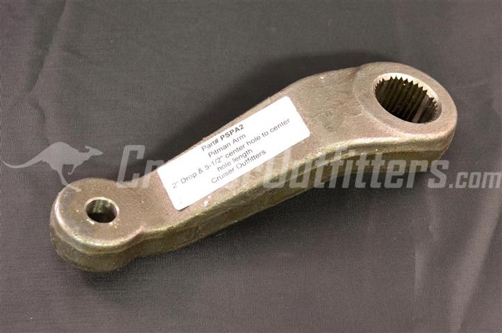
Assemble box plate spacers to match steering gear box. Spacers will need to be cut to length based on your selected steering box as mounting locations change several times throughout the range of Saginaw boxes. One of the spacers can be accommodated with a simple 7/16" washer while the others are thicker and will require use of the spacer material provided. You should have plenty of the material left over, some choose to use the remaining spacer material inside of the frame as a spacer for the two upper box bolts. The goal of the spacers is simply to allow all of the steering gear box mounts to have a firm contact point without allowing the steering box to contact the box plate.
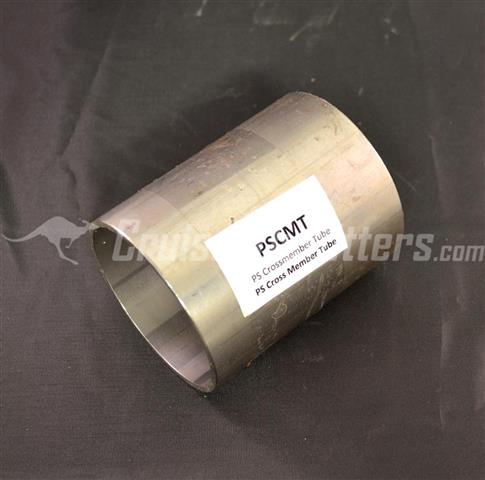
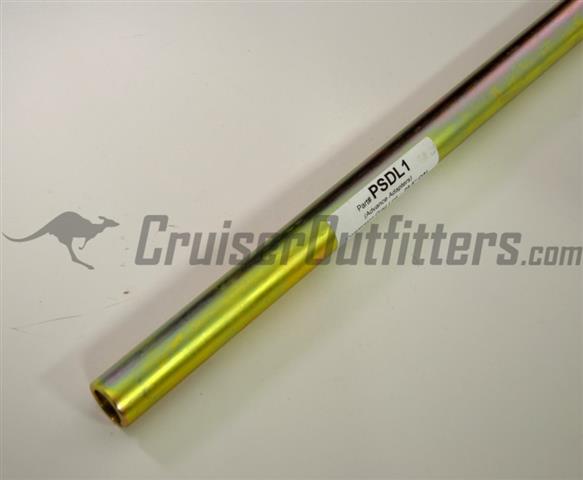
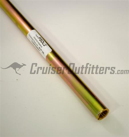
Locate the center of cross member tube insert location using your assembled box plate and loosely fitted steering gear. This should give you the location of your hole with respect to the left to right orientation. The hole needs to be located in the middle of the cross-member in the top to bottom location. With your center hold identified, drill frame using hole saw while following the slight angle that the frame has. Clean up hole and prepare for weld. Push the cross-member tube (PSCMT) into place, ensuring that it is through the layers of cross-member. With the tube pushed through the frame you should have additional material still protruding from the front. Tack weld the tube into place and use a saw-all or cut-off wheel to trim the tube flush with the front of the frame. Add additional tack welds to the rear of the cross-member tube as best as you can. No welds should protrude into the inside diameter of the tube, all welds should be on the face or exterior of the tube.
Tack weld the steering box plate to frame while the steering gear box is still mounted. Ensure your steering box input is lined up with your cross-member tube in both left to right and top & bottom orientations. The top of the power steering box mounting plate should sit flush or near flush with the top of your chassis.
Step 5: Steering Shaft Kit Assembly
Rough assemble steering shaft kit, leaving keyed steering shaft long. Temporarily fit standard yoke to bottom of stock column. Use detent screws to test fit on stock steering column shaft and the bottom joint of the keyed steering shaft.
Temporarily mount steering gear box to frame. Temporarily install steering shaft kit..
Measure and cut keyed steering shaft for ~3" engagement in 4" slip joint assembly. Add key way to rear (upper) end of keyed steering shaft and weld in place at both ends of key stock. Test steering in both directions, inspect for binding or clearance issues.
Step 6: Finalize Welds & Paint
Remove steering gear box and finalize welds on box plate and cross-member tube. Cleanup any welds or slag within the inside dimension of the cross-member tube, prep and paint the tube and the frame plate.
Remove Steering Shaft kit, prep. Finalize welds at key stock, and front (lower) yoke. and paint.
Step 7: Final Assembly of Steering Gear Box & Shaft Kit
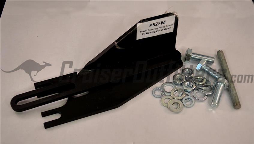
Step 8: PS Pump & Belt Mounting
Refer to instructions that came with your power steering pump mount and pump kit
Step 9: High and Low Pressure Hose
Refer to suggested hose part numbers that were supplied with your power steering installation kit.
(WORK IN PROGRESS, CHECK BACK FOR UPDATES & CALL WITH ANY QUESTIONS/CONCERNS)
|